The purpose of a cable tray system is to support, route, and protect cable as part of the cable management system. Through NEMA and the Cable Tray Institute numerous articles, standards, and other general guidance can be found regarding the proper use and installation of cable tray systems.
The cable tray system is only one component of the cable management system. Another important component is obviously the cable. Therefore, it is also important to understand how to properly apply and install the cables in a cable tray system. To that end this Bulletin is intended to discuss the types of cables most frequently used in cable trays and the wiring methods permitted in cable trays under the National Electric Code (NEC) NFPA 70.
In general, tray rated cables are quality products that have been tested to withstand the rigors of severe environments. They are protected by either a plastic Jacket or metal armor over individual conductor insulations. They can be rated for outdoor, indoor, for corrosive areas, for hazardous locations, or high electrical noise areas. They should be UL listed indicating they have been tested for ratings relative to flammability resistance, mechanical resistance and temperature limitations. Many cable tray rated cables include a crush and impact test as part of the listing and are rated as exposure rated (ER). ER cable is allowed to leave the cable tray for distances up to six feet, as long as it is supported and secured.
In many cases there is more than one type of cable for a particular application, for instance both cables rated as tray cable (TC) and cables rated as metal clad (MC) can be used for 600-volt motor power cables. In all instances cables utilized within a cable tray system should be UL listed and marked as cable tray rated.
The types of cables, allowed in cable trays, and the wiring methods permitted in cable trays can be found in NEC Section 392.10 (A). This Section also lists various corresponding NEC Articles which describes the conditions of use, and installation requirements for a particular class or type of cable. Additional considerations such as fill capacity, allowable ampacity, cable splicing within trays, and securing and supporting cables are addressed in Article 392. Users should be familiar with all these Articles, and check the manufacturer’s specifications, to verify selected cables meet all application requirements and NEC requirements.
The most frequently used tray cables are:
1. Tray Cable – type TC
2. Power Limited Tray Cable – type PLTC
3. Instrumentation Tray Cable – type ITC
4. Metal Clad Cables – type MC
5. Mineral Insulated, Metal Sheathed Cables – type MI
6. Optical Fiber Cables – types OFC thru OFN
7. Communication Cables – types CMP, CMR, CMG, CM, CMX
8. Fire Alarm Cables – type NPLF – NPLFP, FPL-FPLP (CI)
Type TC – Tray Cable – (NEC Article 336) –Power and control tray cable type TC is a factory assembly of two or more insulated conductors, with or without associated bare or covered grounding conductors, under a non-metallic jacket. TC cables are rated for 600 volts and can be used in industrial power or control circuits, where flame retardant cables are desired.
Allowed installations include cable trays, raceways, and outdoor locations where supported by a messenger wire. Type TC cable is UL listed for use in Class 1, Division 2 hazardous locations, and Class 1 control circuits. If identified for such use TC cables may be also be used for direct burial.
In industrial establishments where conditions of maintenance and supervision ensure that only qualified persons will service the installation, the cable is continuously supported, and is protected against physical damage, type TC tray cable that complies with crush and impact requirements (type TC-ER cables) are permitted between a cable tray and the utilization equipment or device. The cable must be secured at intervals not exceeding six feet.
TC cables are not permitted to be installed outside of a cable tray system or raceway with only two exceptions (1) in outdoor locations supported by a messenger wire. (2) Where not subject to physical damage, Type TC-ER cable is permitted to transition freely between cable trays and between cable trays and equipment for distances up to six feet without continuous support.
Type PLTC – Power Limiting Tray Cable – (NEC Article 725)
Type ITC – Instrumentation Tray Cable – (NEC Article 727) – These types of cables are instrumentation cables and are available in shielded or unshielded constructions consisting of multiple single conductors, unshielded or shielded twisted pairs, with or without a metal armor. They have a 300 volt insulation rating and are available in sizes 22 AWG to 12 AWG.
PLTC cables are intended for non-plenum and non-riser Class 3 and Class 2 circuits. They are specially designed for use with power limiting circuits. Application of PLTC cables requires the power supply listing requirements of Article 725.
To avoid this complication an alternative class of cable, Instrumentation Tray Cable (ITC) cable, was added to NFPA 70 – 1996. ITC cable is described in Article 727 and does not have the power supply limitations of Article 725. However, ITC cable may only be installed in instrumentation and control circuits operating at 150 volts or less and 5 amperes or less.
Today many manufacturers dual rate these cables as PLTC / ITC. Cables of either class or the dual rated cables are also available with an ER rating and as such may be installed as previously discussed under TC- ER cables with the exception that PLTC-ER and ITC-ER must be continuously supported using mechanical protection such as struts, angles, or channels and secured every six feet.
ITC cables may be installed in industrial establishments where the conditions of maintenance and supervision ensure that only qualified personnel service the installation. They may be installed either in cable trays, raceways, hazardous locations, as an aerial cable on a messenger, direct burial where identified for the use, under raised floors in rooms containing industrial equipment, under raised floors in information technology equipment rooms.
ITC cables may not be installed with power, lighting, Class 1 circuits that are not power limited, or non-power limited circuits unless they have a metallic sheath and or are terminated within equipment or junction boxes or separations are maintained by insulating barriers.
Even if shielded, both PLTC and ITC cables should be separated from 600-volt power cabling to avoid noise or cross talk. This is generally accomplished through a barrier strip within the cable tray. Whenever possible it is considered best practice to route power and instrumentation cables is separate trays.
Type MC-Metal Clad Cables – (NEC Article 330) – Metal Clad cables are assemblies of one or more insulated circuit conductors with or without optical fiber members enclosed in an armor of interlocking metal tape, or a smooth corrugated sheath. A plastic overall jacket can also be provided.
In appearance MC cables are very similar to armored clad cables type AC cables. It is important to differentiate the two as they should not be confused. Type MC cables contain an equipment ground conductor while type AC cables have an internal bonding strip in contact with the armor. More importantly type MC cables are suitable for outdoor use while type AC cables are not permitted for outdoor use (wet or damp locations).
Type MC cables are widely used in 600 volt and MV power, lighting and control applications. They are permitted for use on services, feeders and branch circuits for power, lighting, control and signaling circuits in accordance with Article 330 and 725 of the NEC. Type MC cables may be installed indoors or outdoors, in wet or dry locations, hazardous locations (Class I, Division I), in cable tray, as aerial cable on a messenger, in any approved raceway, direct burial (where identified), or encased in concrete (where identified). MC cables are not permitted to be
installed where subject to physical damage. MC cables must be supported and secured at intervals not exceeding six feet.
In many industrial application type MC cables, routed in cable trays, have proven to be an excellent economic alternative to wire in conduit.
Type MI-Mineral Insulated, Metal Sheathed – (NEC Article 332)- MI cables are a factory assembly of one or more conductors insulated with a highly compressed refractory mineral insulation, typically magnesium oxide, and enclosed in a liquidtight and gas tight continuous copper or alloy steel sheath. They can also be provided with an overall plastic jacket for additional corrosion protection. Developed in the late 1920’s by the French Navy for submarine electrical wiring systems, properly installed MI cable is commonly considered the safest electrical wiring system available.
Since MI cables use no organic material as insulation (except at the ends), they are more resistant to fires than plastic-insulated cables. MI cables are used in very high temperature applications and /or critical fire protection applications such as alarm circuits, fire pumps, and smoke control systems. MI cables have a two-hour fire rating for critical emergency service and can be used as plenum cabling without an overall nonmetallic jacket. MI cable is also used in process industries handling flammable fluids where small fires would otherwise cause damage to control or power cables. MI cable is also highly resistant to ionizing radiation and are used in applications at nuclear power facilities and nuclear physics apparatus.
MI cables are suitable for 300 volt and 600 volt applications and are permitted for services, feeders, and branch circuits for power, lighting, control, and signal circuits. They may be installed in dry, wet or continuously moist locations, indoor or outdoor, exposed or concealed, where embedded in plaster, concrete, or other masonry, in hazardous locations, where exposed to oil or gasoline, in underground runs, or in cable trays.
MI cables are not permitted in underground runs unless protected from physical damage, where necessary. MI cables are also not permitted where exposed conditions are destructive and corrosive to the metallic sheath, unless additional protection is provided.
When installed in cable trays MI cable shall comply with NEC Article 392.30(A) ensuring the cable tray is supported at intervals in accordance with the installation instruction.
Type OFN-OPC- Optical Fiber – (NEC Article 770) – Fiber optic (or “optical fiber”) refers to the medium and the technology associated with the transmission of information as light impulses along a glass or plastic wire or fiber. Fiber optic wire carries much more information than conventional copper wire and is far less subject to electromagnetic interference.
An optical fiber cable is a cable containing one or more optical fibers that are used to carry light. The optical fiber elements are typically individually coated with plastic layers and contained in a protective tube suitable for the environment where the cable will be deployed.
Different types of cable are used for different applications, for example long distance or providing a high-speed data connection between different parts of a building.
Optical Fiber (OF) cables are rated as conductive or non-conductive. OF cables rated as conductive contain non-current carrying members such as a metallic sheath or armor. OF cables rated as non-conductive contain no electrically conductive materials. They are also rated based upon U.L. flame test(s) and are marked with their respective NEC building fire rating.
NEC Article 770.113 (H) Permits the following types of optical fiber cables to be supported in cable trays.
- OFC: Optical fiber, conductive
- OFN: Optical fiber, nonconductive
- OFCG: Optical fiber, conductive, general use
- OFNG: Optical fiber, nonconductive, general use
- OFCP: Optical fiber, conductive, plenum
- OFNP: Optical fiber, nonconductive, plenum
- OFCR: Optical fiber, conductive, riser
- OFNR: Optical fiber, nonconductive, riser
NEC Table 770.154(a) Applications of Listed Optical Fiber Cables details where these types of cables and cable trays may be used within buildings, and which type of cable may be used in cable trays. In summary:
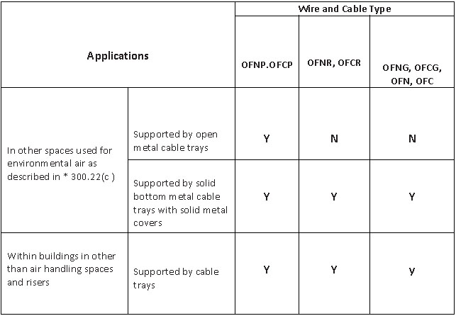
* Example – The space over a hung ceiling used for environmental area handling purposes.
Note: Where permitted the cables and cable trays must be installed per the installation methods described in 770.110 and 770.113.
OFN (non-conductive) cables are permitted to occupy the same cable tray with conductors for electric light, Class 1, non-power limiting fire alarm, Type ITC, or medium power net-work powered broadband communications circuits operating at 1000 volts or less. OFC (conductive) cables must be separated from these other types of cables.
Cable tray fill capacities for optical fiber cables are not addressed in NEC Article 770 nor Article 392. Designers and installers should refer to the cable manufacturer for guidance.
Type CMP – CMX Communication Cables – (NEC Article 800) Similar to optical fiber, communication cables are used to send information signals. This can be accomplished with coaxial conductors, copper conductors, or twisted wire pairs. These cables are used in a wide variety of applications, including recording studios, data transmission, radio transmitters, intercoms, electronic circuits, and in applications where RF shielding is needed. The NEC defines communication cables as a factory assembly of two or more conductors having an overall covering. A covering over the conductor assembly may include one or more metallic members, strength members, or jackets. Ethernet cables are a common type on communication cable and are often listed and installed according to NEC Article 800.
Since communication cables are often routed through air circulation spaces which often contain very few fire barriers, they need to be coated in material that won’t contribute to the spreading of flames. Communication cables are test by UL and are (rated) marked based on their fire propagation properties and as such their suitability to be applied in certain building areas (environmental air-handling spaces).
NEC Article 800 defines these markings, areas of permitted use and provides a hierarchy for cable substation.
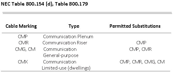
NEC Table 800.154(a) Applications of Listed Communication Wires and Cable in Buildings- Further details the application for each type of communication cable including, applications where cable trays may be used within buildings, and which type of cable may be used in cable trays. In summary:
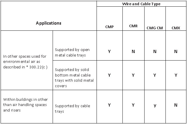
* Example – The space over a hung ceiling used for environmental area handling purposes.
Note: Where permitted the cables and cable trays must be installed per the installation methods described in 800.113.
Type FPL-FPLP (CI), NPLF – NPLFP (CI) Fire Alarm Cables – (NEC Article 760) Fire alarm circuits and cables are classified as either power limited or non-power limited. Cables for either type circuit may be furthered classified as (CI) indicating they have meet the requirements to ensure continued operation of critical circuits during a specified time under fire conditions.
Power-Limited-Fire Alarm (PLFA) circuits are fire alarm circuits powered by a source that complies with 760.121 (listed PLFA or Class 3 transformer, Listed PLFA or Class 3 power supply, listed equipment marked to identify the PLFA power source.)
As with communication and optic fiber cables, PLFA fire alarm cables are also further marked relative to their fire propagation potential, indicating the permitted areas of use. There is also a hierarchy for permitted substitution for cables used in power-limited circuits, which includes communication cables.

Power limited fire alarm cables (FPL-FPLP) are solid or stranded copper. Multi-conductors cannot be less than 26 AWG. Single conductors cannot be less than 18 AWG. FPL cables must have a voltage insulation rating of not less than 300 volt. Power-limited fire alarm cables are not permitted to be placed in cable trays with electric light, power, Class 1, non-power limited fire alarm, and medium-power network-powered broadband communication circuits unless they are separated by a barrier. You cannot install audio system circuits [760.139(D), 640.9(C)] (using Class 2 or Class 3 wiring methods) in the same cable or raceway with PLFA conductors or cables.
NEC Table 760.154 Applications of Listed PLFA Cables in Buildings – details the application for each type of PFLA cable including applications where cable trays may be used within buildings and which type of cable may be used in cable trays. In summary:
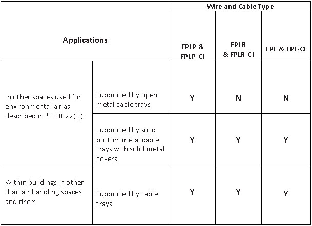
* Example – The space over a hung ceiling used for environmental area handling purposes.
Note: Where permitted the cables and cable trays must be installed per the installation methods described in 760.130 and 760.145.
Non-Power – Limited Fire Alarm (NPLFA) circuits are fire alarm circuits powered by a source that complies with NEC 760.41 and 760.43 (power source shall not exceed 600 volts and must contain overcurrent protection devices (OCPDs). OCPDs must not exceed 7A for 18 AWG or 10A for 16 AWG conductors. You must locate the OCPDs at the point where the conductor receives its supply.)
As with communication, optic fiber cables, and PLFA cables NPLFA fire alarm cables are also further marked relative to their fire propagation potential, indicating the permitted areas of use.
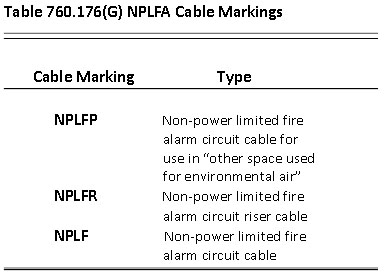
Note that Multi-conductor non-power-limited fire alarm circuit cables, Types NPLFP, NPLFR, and NPLF, shall not be installed in exposed air ducts.
Non-power limited fire alarm cables are also solid or stranded copper. Size 18 AWG and 16 AWG conductors are permitted to be used, provided they supply loads that do not exceed 6 ampere for 18 AWG and 8 ampere for 16 AWG conductors. Conductors larger than 16 AWG shall not supply loads greater than the ampacities given in NEC 310.15, as applicable.
NPLFA and Class 1 fire alarm circuits are permitted to occupy the same cable, enclosure or raceway provided all conductors are insulated for the maximum voltage of any conductor in the enclosure or raceway. Where connected to the same equipment, power supply and NPFLA circuits are permitted in the same cable, enclosure or raceway.
When installed in cable trays, fire alarm circuit conductors, as well as any tray cable should comply with NEC Article 392 Cable Trays. In particular sections 392.22 (Number of Conductors), 392.60 (Grounding and Bonding), and section 392.80 (Ampacity of Conductors).
Although less commonly used, several other types of cables are permitted to be installed in cable trays. These include: Type AC, CATV, NM, NMC, NMS, SE, USE and UF. As with the cables discussed in this Bulletin users should refer to the associated NEC Article for the proper wiring methods for each type of cable.
Section 392.10 (A) also permits various other raceways to be installed in cable tray i.e. EMT, RMC and PVC conduits. However, generally these types of raceways are more commonly and economically supported with strut products rather than cable tray.
This article offers clear idea for the new viewers of blogging, that truly how to do blogging.
Here is my page; 토토커뮤니티