Cable tray wiring systems have excellent safety and dependability records. These excellent records are the result of cable tray’s unique features plus the proper design and installation of the cable tray wiring systems. The intent of this article is to review grounding practices for cable tray wiring systems. The Equipment Grounding Conductors are the most important conductors in the electrical systems. The Equipment Grounding Conductor is the electrical circuit’s safety conductor.
When designing a cable tray wiring system, the designer should evaluate the National Electrical Code’s (NEC) Equipment Grounding Conductor (EGC) options that are applicable for the project.
Evaluate the following Options:
1. Use the cable tray as the EGC. [The cable tray may only be used as an EGC in qualifying facilities as stated in NEC Section 318-3(c)].
2. Use a single conductor cable as the common EGC for all the circuits in the cable tray [NEC Section 318-3(b)(1) Exception 2].
3. Use individual EGC conductors in each multiconductor cable in the cable tray (NEC Section 250-95).
4. Parallel the EGCs with the cable tray.
The requirements for the EGCs are covered in several Sections of the NEC.
NEC Section 110-10. Circuit Impedance and Other Characteristics. States that the components and characteristics of a circuit must be properly selected and coordinated so that a fault (short circuit) will be cleared without extensive damage to the electrical components of the circuit.
NEC Section 250-1(f). Fine Print Note (FPN) No. 2 states that conductive materials enclosing electrical conductors or equipment are grounded to limit the voltage to ground on these conductive materials and bonded to facilitate the operation of the over-current devices under ground fault conditions.
NEC Section 250-51 states that the effective grounding path shall be: permanent and electrically continuous, have the capacity to safely conduct any fault current imposed on it, have sufficiently low impedance to limit the voltage to ground and to facilitate the operation of the protective devices.
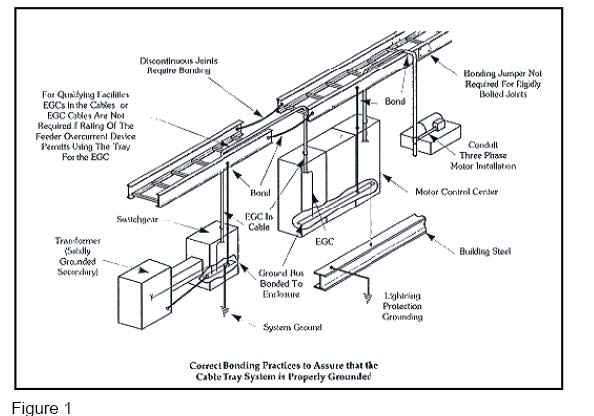
NEC Section 318-6(a) states that cable tray is not required to be mechanically continuous but it must be electrically continuous and bonding shall be in accordance with NEC Section 250-75.
It is desirable that a line to ground fault be quickly cleared by the circuit protective device. While the ground fault exists, the facility personnel and also the facility may be exposed to unsafe conditions. Voltages may be distributed through the facility’s metallic components in such a manner that they may produce conditions which can result in the electrocution or injury of the facility personnel who physically contact the energized metallic components. There is the potential for fire damage to the facility if the fault current electrical arcs become fire ignition sources.
A Look at the EGC Options Available for Cable Tray Systems.
1. Cable Trays as the EGCs.
NEC Section 318-3(c) Equipment Grounding Conductors states that metallic cable trays shall be permitted to be used as EGCs where continuous maintenance and supervision ensures that qualified persons will service the installed cable tray system and that the cable tray complies with the provisions of NEC Section 318-7. Grounding.
This means that cable tray may be used as the EGC in any qualifying facility. There is no restriction as to the type of facility in which cable tray may be used as the EGC. The qualifying restriction is based on the expertise of the facilities electrical maintenance staff. The involved electrical staff must be qualified.
Metal cable trays are Underwriters Laboratories (UL) Classified with regard to suitability for use as EGCs. The Classification Marking states: ” Classified by Underwriters Laboratories Inc. as to its Suitability as an Equipment Grounding Conductor.” Cable tray is not Listed by UL, it is classified by UL as an EGC.
The cross-section area of metal that is available for use as an EGC is shown in the Manufacturers catalogs for the various cable trays. This is the sum of the cross-section areas of the two side rails. For one piece construction cables trays, the total cross section area is the sum of the side rail’s cross sections plus the solid bottom’s cross section area. If the cable tray’s bottom contains ventilation openings, the ventilation openings reduces the cross section area of the cable tray’s bottom available for EGC service. If the cable tray is to be used an EGC, it should be specified in the purchase order and the manufacturer will mark or place a permanent information label on the cable tray’s side rail. This marking or information label will specify the cable tray’s cross section EGC metal area and state that the cable tray is UL Classified for Use as an EGC. It is not necessary to apply conductive compound on the standard cable tray splice plate connections or to install bonding jumpers across the standard cable tray splice plate connections for aluminum or steel cable tray.
Table 318-7(b)(2) “Metal Area Requirements for Cable Trays Used as Equipment Grounding Conductors” shows the minimum cross section metal area that is required for aluminum or steel cable trays to be used as the EGC based on the highest rating of any protective device (the fuse rating or circuit breaker trip setting) for the circuits in the cable tray. If the cable trays cross section area is insufficient for the protective device rating, the cable tray can’t be used as the EGC and a separate EGC single conductor cable must be installed in the cable tray or each multiconductor cable must contain an EGC conductor. Connections of conduits and/or cables (Bonding and/or EGC) to the cable trays should be made with UL Listed Connectors that are properly installed to insure that there is good electrical continuity between the cable tray and the conduits and/or cables.
As per NEC Section 318-7(a), all metal cable trays must be grounded as required by NEC Article 250 regardless of whether or not the cable tray is being used as an EGC.
2. Single Conductor EGC Cables in Cable Trays.
NEC Section 318-3(b)(1) Exception No. 2 states that insulated, covered or bare single conductors that are #4 AWG or larger may be used as EGCs cables in cable trays.
When a single conductor EGC cable is used, the single conductor EGC cable must be sized for the fuse rating or circuit breaker trip setting (NEC Table 250-95) of the highest capacity circuit in the cable tray that would potentially utilize the single conductor EGC cable if a ground fault should occur.
In a moisture laden environment, a bare copper EGC should not be installed in an aluminum cable tray due to the potential for electrolytic corrosion of the aluminum cable tray. For such installations, it is best to use a covered or insulated conductor and to remove the covering or insulation where bonding connections are made to the cable tray, bonding jumpers, raceways, equipment enclosures, etc. with UL Listed tin or zinc plated connectors.
While it is not a necessity, there are benefits to bonding the single conductor EGC cable to the cable tray run every 50 to 100 feet with a UL Listed connector. This puts the cable tray electrically in parallel with the EGC cable. If a ground fault occurs, this practice can result in lower voltages to ground being impressed on fault energized metallic facility components. The electrically paralleled cable tray and the EGC cable become a low impedance EGC (See Option #4). The EGC cables should be securely tied to cable tray every 10 to 20 feet so that under fault conditions, the magnetic forces do not throw the EGC out of the cable tray.
3. Multiconductor Cables with EGCs in Cable Trays.
Multiconductor cables can be specified that contain their own EGC. EGC conductors in multiconductor cables may be bare, covered or insulated. If covered or insulated, the outer finish must be green or green with one or more yellow stripes [See NEC Section 250-57(b)]. In qualifying facilities, any insulated conductor in a multiconductor cable may be permanently identified as an EGC by one of the three indicated methods indicated in NEC Section 250-57(b) Exception No. 4.
The EGCs of Paralleled Multiconductor Cables in Cable Trays.
A significant change was made in NEC Section 250-95. Size of Equipment Grounding Conductors for the 1993 and 1996 NECs which impacts on the paralleling of standard multiconductor cables in cable trays. This change requires an increase in the size of the EGCs in three conductor cables when the phase conductors are paralleled and the EGCs are paralleled or a separate EGC of the proper size must be installed in the cable tray.
The proposals that were accepted to revise NEC Section 250-95 didn’t contain any documented safety problems. The submitter’s substantiation was that conductors of cables are permitted to be paralleled so the single sized EGC as applied to raceway systems should be applied to multiconductor cables. As a result “or cable” was placed after the word “raceway” throughout NEC Section 250-95.
There haven’t been any public facts presented on any safety or technical problems due to operating standard three conductor cables with standard sized EGCs in parallel. This has been a common industrial practice for several decades. In many Chemical, Plastics and Textiles Manufacturing Facilities, the 480 volt feeders (Type TC Cables) from the substations to the motor control centers have been paralleled standard three conductor cables with the standard sized EGCs paralleled since the early 1960s.
For paralleled three conductor cables installed in cable tray to be in compliance with the 1996 NEC, one of the following options must be selected:
A. Order special three conductor cables which contain larger sized EGCs. The size of the EGCs will depend on the rating or setting of the circuit’s protective device as per NEC Table 250-95. This means that the size of the EGCs is dependent on the number of three conductor cables that are paralleled to obtain the circuit capacity desired.
B. Use three conductor cables without EGCs and install a single conductor EGC in the cable tray or use the cable tray as the EGC in qualifying installations as per Section 318-3(c).
C. Use standard three conductor cables with standard size EGCs and parallel the EGCs that are in the cable assemblies with the single conductor EGC (Sized as per Table 250-95) in the cable tray or with the cable tray if it is used as the EGC. This meets the NEC Section 250-95 requirements.
4. Electrically Paralleling the Single Conductor EGC and the Cable Tray.
Electrically paralleling the single conductor EGC with the Cable Tray by bonding the single conductor EGC to the cable tray every 50 to 100 feet produces an installation that may provide some degree of improved electrical safety for a facility and its personnel during ground fault conditions. The bonding of the cable tray run to the single conductor EGC every 50 to 100 feet is not required by the NEC but it is a desirable optional practice.
A comparison is made below for an installation where the single conductor EGC isn’t electrically paralleled with the cable tray and for an installation where the single conductor EGC is paralleled with the cable tray.
As a basis for a simple comparison of the two cases, the following assumptions are made:
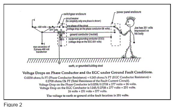
System: One phase (277 volts) of the secondary of a 480 volt wye connected transformer is shown.
Conductors: The phase conductor is a 500 kcmil copper conductor with 75 degree C insulation. It is rated for 380 amperes with no de-rating for ambient temperature conditions. The protective device is rated at 400 amperes. The EGC is a # 3 AWG copper (NEC Table 250-95). The cross section of the Aluminum cable tray side rails
is 2 square inches. The conductivity of the cable tray aluminum is about 55 percent that of copper.
Resistance of the 500 kcmil copper conductor is 0.0258 ohms/k FT.
Resistance of the #3 AWG copper conductor is 0.245 ohms/k FT.
Resistance of the aluminum cable tray is approximately 0.0143 ohms/k FT.
Resistance of the paralleled #3 EGC and the aluminum cable tray is 0.0135 ohms/k FT. [Resulting resistance of the paralleled conductors is R1 x R2/R1 + R2. = (0.0143)(0.245)/0.0143) + (0.245) = 0.0135 ohms].
Assumptions: To simplify the examples, resistance values are used instead of impedance. In an actual installation, impedance would determine the fault current magnitude and the voltage drops. The voltage drop across the arc of the fault is omitted. It is assumed that all the return fault current will be confined to the single conductor EGC or the single conductor EGC and the cable tray when they are electrically paralleled. It is assumed that the phase conductor, the EGC and the aluminum cable tray are all the same lengths
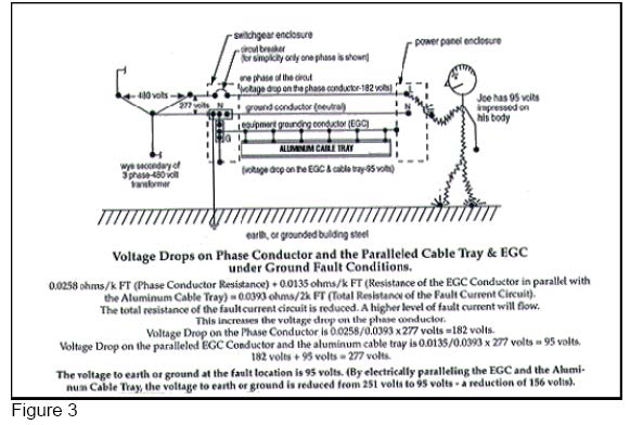
Connecting the cable tray electrically in parallel with the single conductor EGC is an option worth considering. The resulting reduced impedance of the EGC may provide for improvements in the facilities overall electrical safety. The reduced impedance of the fault circuit will produce a higher fault current magnitude which will result in the protective devices de-energizing the faulted circuit quicker. The shock potential to facilities personnel is lower (In the example the 95 volts is still potentially deadly but it is not as apt to be fatal as is the 251 volts). The lower potential to ground at the fault may result in lower magnitudes of stray fault current flowing through the facilities metallic items. This reduces the chances of electrical arcs occurring which can be fire ignition sources.