What NEC states for max. voltage drop?
The NEC states in an Informational Note that a maximum voltage drop of 3% for branch circuit conductors, and 5% for feeder and branch circuit conductors together, will provide reasonable efficiency of operation for general use circuits.
For sensitive electronic loads, circuits should be designed for a maximum of 1.5% voltage drop for branch circuits at full load, and 2.5% voltage drop for feeder and branch circuits combined at full load.
Four practical approaches can be used to minimize voltage drop problems:
- Increasing the number or size of conductors
- Reducing the load current on the circuit
- Decreasing conductor length, and
- Decreasing conductor temperature
1. Increase the Number or Size of Conductors
Parallel or oversized conductors have lower resistance per unit length than the Code-required minimum-sized conductors, reducing voltage drop and increasing energy efficiency with lower losses than using the Code-required minimum-sized conductor.
To limit neutral-to-ground voltage drop, install a separate, full-sized neutral conductor for each phase conductor in single-phase branch circuit applications.
For three-phase feeder circuits, do not downsize the grounded conductor or neutral. For three-phase circuits where significant non-linear loads are anticipated, it is recommended to install grounded or neutral conductors with at least double the ampacity of each phase conductor.
2. Decrease Load Current
Limiting the amount of equipment that can be connected to a single circuit will limit the load current on the circuit. Limit the number of receptacles on each branch circuit to three to six.
For residential applications, install outdoor receptacles not to exceed 50 linear feet between receptacles, with a minimum of one outdoor receptacle on each side of the house, and with individual branch circuits with a minimum of 12 AWG to each receptacle.
3. Decrease Conductor Length
Decreasing conductor length reduces the resistance of the conductor, which reduces voltage drop. Circuit lengths are usually fixed, but some control can be exercised at the design stage if panels or subpanels are located as close as possible to the loads, especially for sensitive electronic equipment.
4. Adjust Conductor Temperature
The conductor temperature is in turn dependent on each of the three factors above, since more heavily loaded circuits will run hotter.
Conductor temperature is a major factor in conductor resistance, and therefore in voltage drop. The temperature coefficient of electrical resistance for copper, α, is 0.00323/°C, or a resistance change of about 0.3% for each °C of temperature change. The effect of temperature can be determined by the following equation:R2 = R1 [1 + α · (T2 – T1)]
Where R1 is the resistance (Ω) at temperature T1 and R2 is the resistance at temperature T2.
Temperature T1 is often referenced at 75°C. As noted, voltage drop is a particular concern at high conductor loadings, where conductor temperatures will also be high.
Examples //
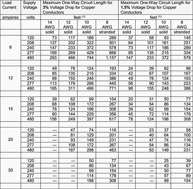
The interactions between conductor sizes, load currents, and conductor lengths at various supply voltages are shown in Table 1 below.
The combinations of various load currents – from 8 to 30 amperes – andsupply voltages – from 120 to 480 volts – are shown in the left two columns of the table. The next four columns show the maximum circuit lengths(one-way) for four different conductor sizes to attain a 3% voltage drop. The last four columns are maximum lengths for an allowable 1.5% voltage drop.
For example, a 12 ampere load in a 120 volt circuit on a 14 AWG conductor will exceed a 3% voltage drop (3.6 volts) if the circuit is longer than 49 feet from source to load.If the conductor is upsized to 12 AWG the allowable distance increases significantly to 78 feet each way (an increase of 59%). If the load is increased to an allowable maximum of 15 amps for 14 AWG conductor, the allowable length is only 39 feet, and moving to a 12 AWG conductor would increase this to 62 feet (also an increase in length of 59%).
The 1.5% data values are given for situations when it is necessary to comply with NEC 647.4(D).
Verify the equipment’s actual requirements whenever possible. The much tighter 1.5% voltage drop allowance on the right side of Table 1 cuts the allowable lengths to only 1/2 of their values at 3% voltage drop. Conductor upsizing is often mandated for the protection of sensitive electronic equipment. Voltage drop can be minimized if the panel or subpanel can be located as close as possible to the point of use.
Perusal of Table 1 inevitably leads to the conclusionthat voltage drop is too often ignored.
For example, the lengths of many branch circuits in 14 AWG wire exceed even the 3% voltage drop of 39 feet, not to mention the tighter 1.5% drop of 20 feet. When this happens, the integrity of both the wiring and of many loads is put in jeopardy.
Table 1 – Maximum Recommended Lengths of Single-Phase Branch Circuits, as a Function of Load Current, Supply Voltage, and Conductor Size, for Both 3% and 1.5% Voltage Drops.

Notes regarding above table //
- Branch circuit lengths shown in the table are half the calculated distance from the V = IR Ohm’s Law formula, rounded to the nearest 1-foot increment. For example, the calculated value for 14 AWG at a load current of 15 amps and a supplied voltage of 120 volts using the value of 3.07 Ω/1,000 feet for a 3% drop (or 3.6 volts) is 78 feet. Since the conductors must carry the current over and back, the allowable one-way distance from source to load is 39 feet.
- For convenient use of the NEC tables, loads are assumed to be purely resistive, direct-current loads. Alternating current values differ only slightly. Harmonics or inductive loads may accentuate voltage drop, and decrease recommended circuit lengths.
- Calculations are based on resistance values found in NEC Chapter 9, Table 8 for solid, uncoated copper conductors. For 14 AWG, the resistance is 3.07 Ω/1,000 feet, for 12 AWG it is 1.93 Ω/1,000 feet, for 10 AWG it is 1.21 Ω/1,000 feet, and for 8 AWG (stranded) it is 0.778 Ω/1,000 feet. Conductor temperatures higher than 75°C (167°F) will increase these resistances, and vice versa.
Reference: Recommended Practices for Designing and Installing Copper Building Wire Systems – Copper Development Association Inc.