All materials expand and contract due to temperature changes. It is important that cable tray installations incorporate features which provide adequate compensation for their thermal contraction and expansion.
1993 NEC Section 300-7 (b) states that “Raceways shall be provided with expansion joints where necessary to compensate for the thermal expansion or contraction.” In 1993 NEC Article 318 there are no requirements for the handling of the thermal contraction and expansion of cable tray. This subject is addressed in the NEMA Standards Publication No. VE 1 “Metallic Cable Tray Systems” Section 6.8.
There are expansion joint splice plates and bonding jumpers available from cable tray manufacturers. A cable tray support should be located within 2 feet of each side of the expansion joint splice plates position. The cable trays must not be clamped to each support so firmly that the cable tray cannot expand without distortion. The cable tray needs to be anchored at the support closest to the midpoint between the expansion joints with hold down clamps and secured by expansion guides at all other support locations. The expansion guides allow the cable tray to slide back and forth as it contracts and expands. If provisions for the thermal contraction and expansion of the cable trays are not provided for where there are large summer to winter temperature extremes (example: roof top installations); there is the potential for the cable trays to tear loose from their supports, for the cable trays to bend (snake), or for bolt hole elongations at the splice plate areas.
Bridges and some other structures have expansion joints. Installing expansion joints in the cable tray runs only at the structure expansion joint positions, does not normally provide a valid solution to adequately compensate for the cable tray’s thermal contraction and expansion. The materials of the structures and the cable trays are different. They will have different values of thermal contraction and expansion. They each require unique solutions for their thermal compensation and expansion.
In the NEMA Metallic Cable Tray Systems Standard VE 1, Section 6.8 Thermal Contraction and Expansion. VE 1 Table 6-1 shows the allowable lengths of steel and aluminum cable tray between expansion joints for the temperature differential values.
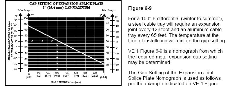
For a 100° F differential (winter to summer), a steel cable tray will require an expansion joint every 128 feet and an aluminum cable tray every 65 feet. The temperature at the time of installation will dictate the gap setting.
VE 1 Figure 6-9 is a nomograph from which the required metal expansion gap setting may be determined.
The Gap Setting of the Expansion Joint Splice Plate Nomograph is used as follows per the example indicated on VE 1 Figure 6-9.
Step 1. Plot the highest expected cable tray metal temperature on the maximum temperature vertical axis. Example’s Value = 100° F.
Step 2. Plot the lowest expected cable tray metal temperature on the minimum temperature vertical axis. Example’s Value: = -28° F.
Step 3. Draw a line between these maximum and minimum temperature points on the two vertical axis.
Step 4. To determine the required expansion joint gap setting: Plot the cable tray metal temperature at the time of the cable tray installation on the Maximum temperature vertical axis (Example’s Value: 50° F). Project over from the 50° F point on the maximum temperature vertical axis to an intersection with the line between the maximum and minimum cable tray metal temperatures. From this intersection point, project down to the gap setting horizontal axis to find the correct gap setting value (Example’s Value: 3/8 inch gap setting). This is the length of the gap to be set between the cable tray sections at the expansion joint splice plate location.
For simplicity, the bonding jumpers around the expansion joint splice plates should be sized to match the fault current capacity of the cable tray side rails or the cable tray cross section for one piece construction cable trays. Following such a practice will not require that the bonding jumpers must be changed if higher capacity circuits (that require increases in the protective device sizes or setting) are installed in the cable tray at a later date. If it is known that there will not be any additions of higher rated circuits and that the rating of the protective devices will not be increased, the bonding jumpers may be sized as per 1993 NEC Table 250-95.
Can someone recommend White and Nude Lingerie? Cheers x